


THE PROCESS
HARDWARE AND TOOLS USED
- Laser cutter Model Trotec Speedy 300 x2 Power 60 Watts Cutting surface 74 x 44 cm (29″ x 17″) Usable materials Paper, cardboard, acrylic (1/2″ max), wood (1/4″ max)
- Vinyl cutter : Roland CAMM-1 PNC-1000 Cutting surface 24po Usable materials Vinyl, paper
- Roland cut studio
- Inkscape
- 6mm Russian plywood
- Adobe Illustrator
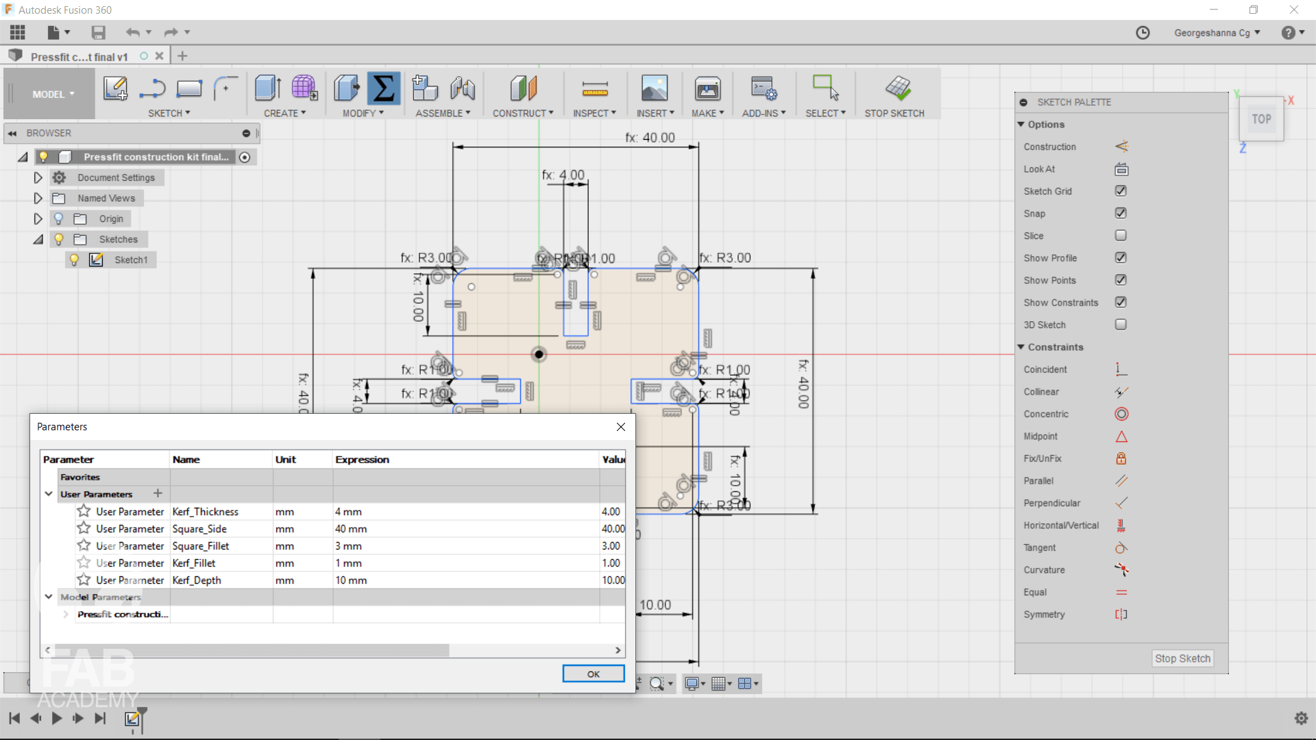
MODELLING THE PART USING FUSION 360
For this assignment I decided to use Fusion 360 because I wanted the modular design to be parametric so for modelling the press-fit construction kit first I started with drawing the desirable shape and then I started adding Sketch Constraints in order to set relation between dimensions Parametric design is very helpful because it brings engineers many advantages. For instance, once you have made a part that will be used in many models, then the part can be archived so that in the future it can be recalled rather than remodeled. And, because it is possible to embed intelligence with a design, it allows engineers to pass this design intelligence to other engineers throughout the life-cycle of the product. With a parametric approach, it is possible to add constraints to parts, meaning that they cannot be altered by mistake later on in the design process. In other words, constraints are a way of ensuring that any modifications made to the design are done so with design intent in mind.
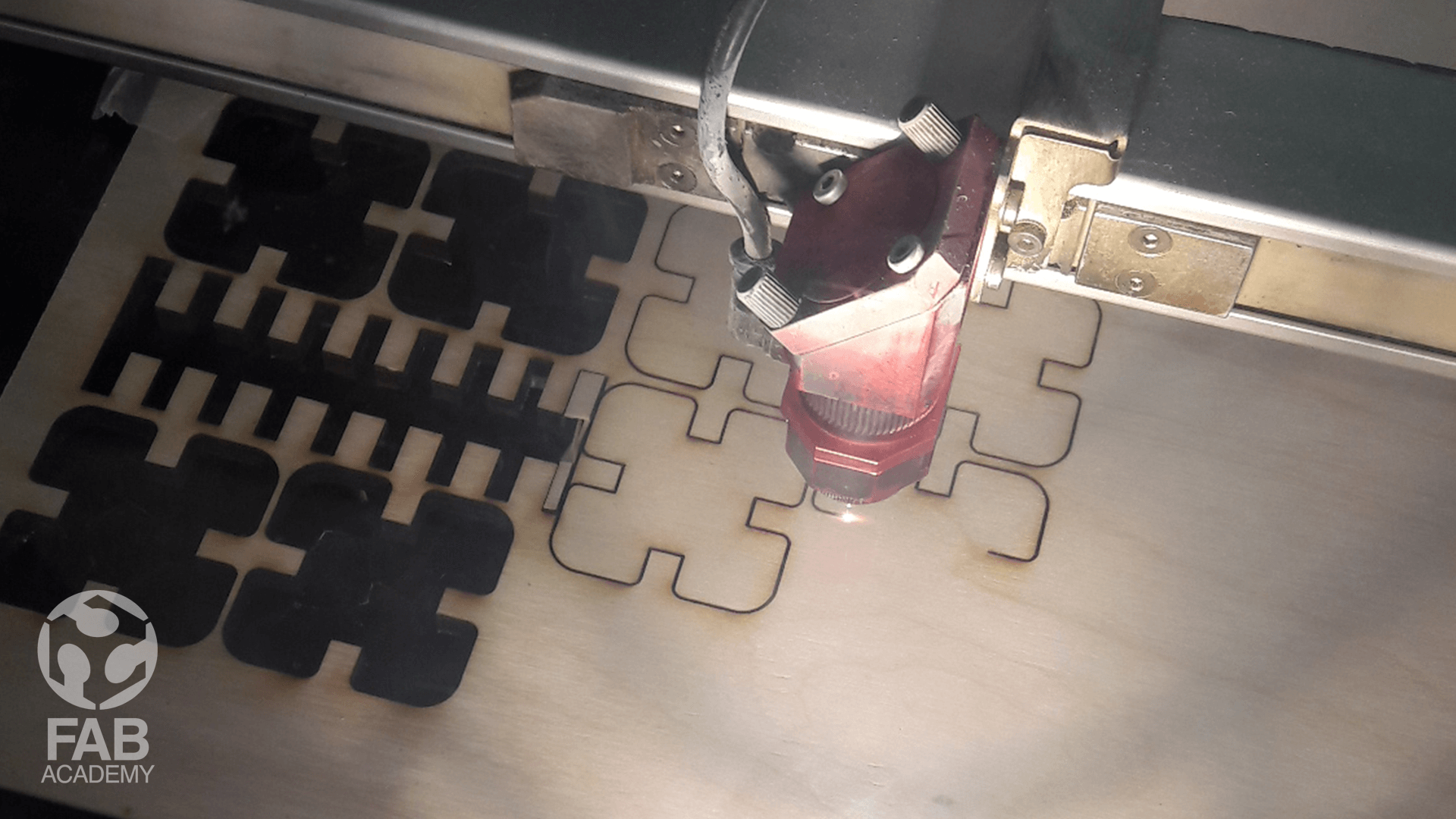
CUTTING AND ASSEMBLING THE PARTS TOGETHER
However, After finalizing the design in fusion 360 I exported the sketch in DXF format. Exporting 2D objects from Fusion 360 is pretty easy all you have to do is right click on the sketch layer and choose save as DXF.
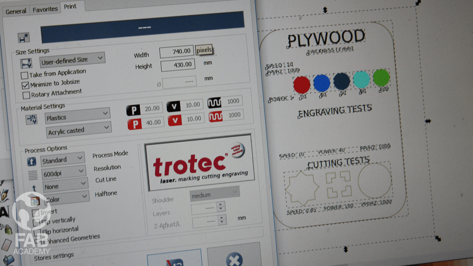
Then I imported the dxf file into Inkscape and changed the color of the edges to red ( RGB Value 255,0,0) in order to tell the laser cutter software that use red color for cutting. The printer's software called (JobControl) it is a very easy to use and user friendly and it has many features like it can Save laser settings (size, material, resolution, cut lines, etc.) for repeating jobs. Saves setup time and reduces the risk of errors in addition to that adding, changing or deleting materials is extremely easy. In the tutorial section below I've included a link for how to use JobControl X.
Below are the settings I used for cutting the wooden modular parts :
( FOR CUTTING )
POWER : 100 - SPEED : 0.80 - PPI / HZ : 1000
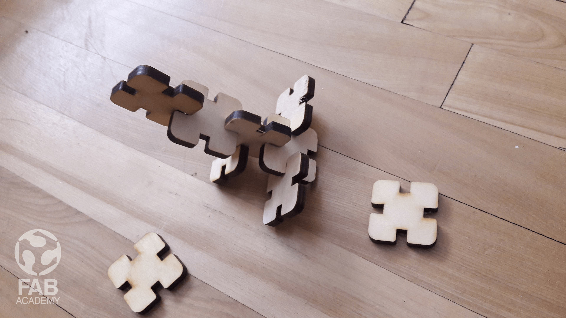
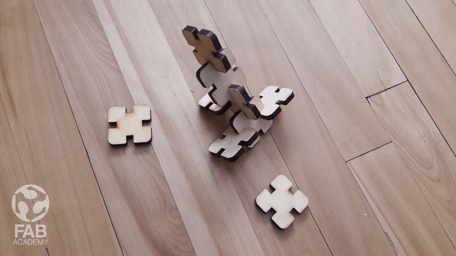
Finaly, After all the parts were cutted I started assambling them in many diffrent ways as you see in images #4 #5
MAKING TEST PARTS AS A GROUP ASSIGNMENT
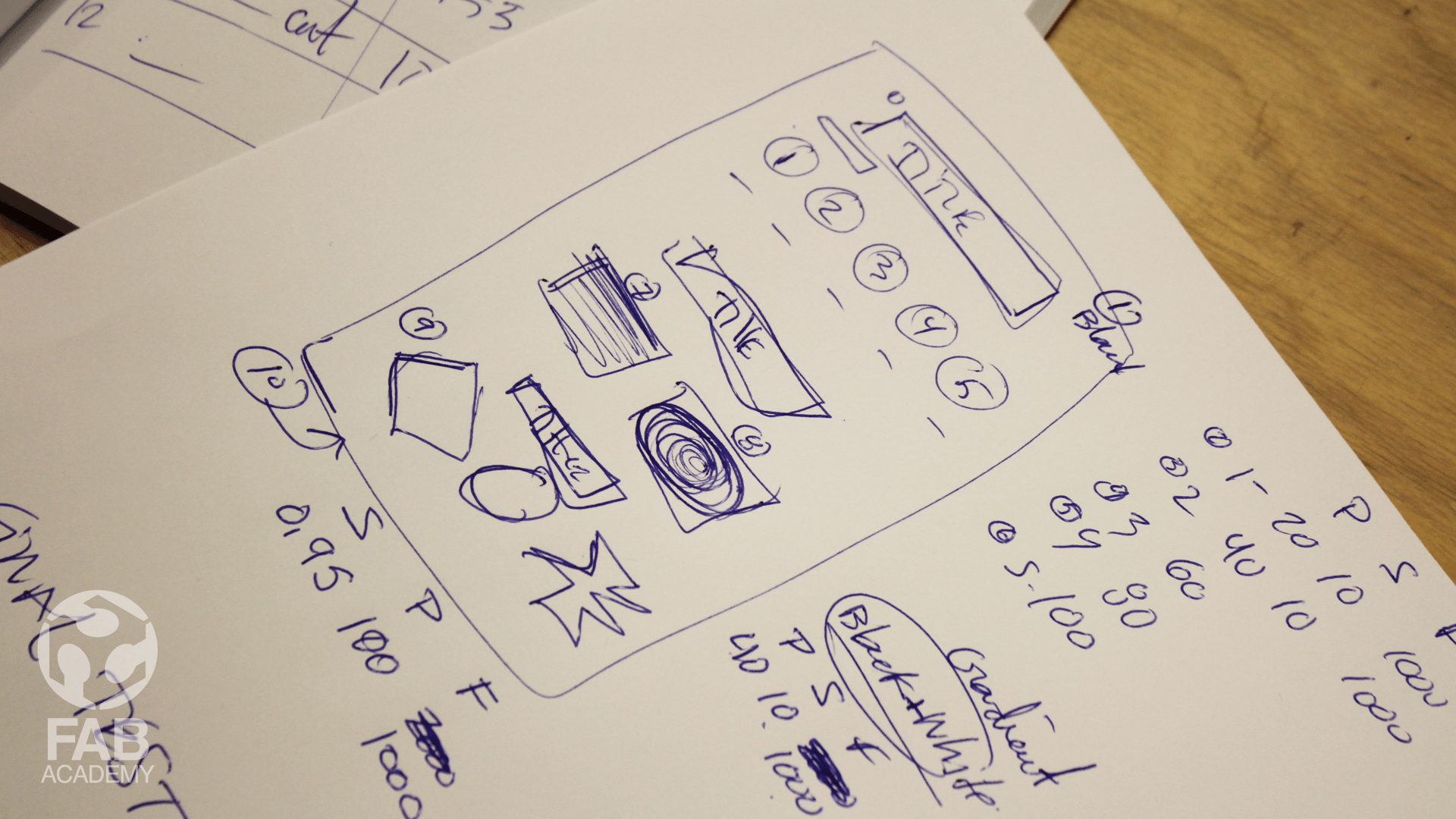
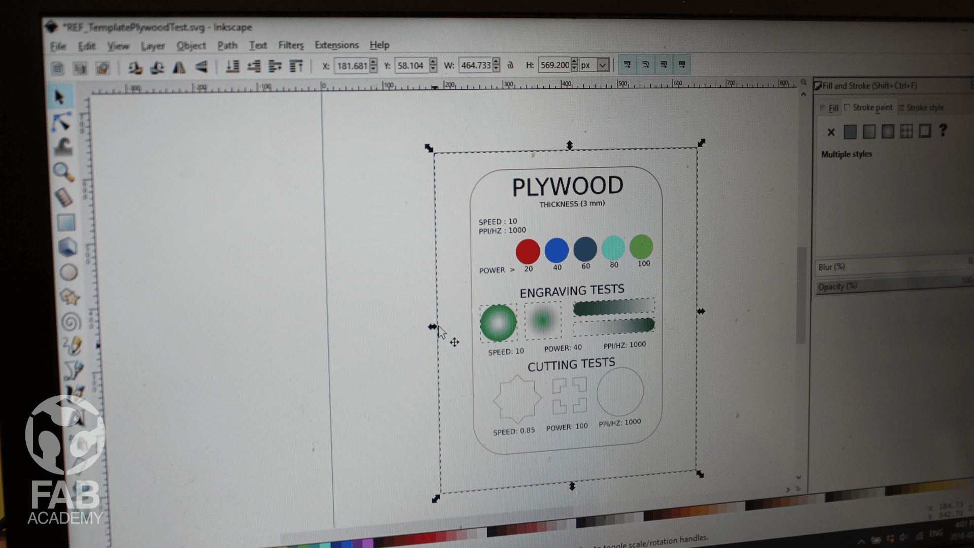
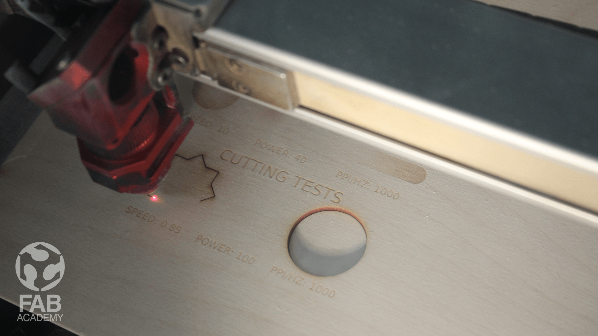
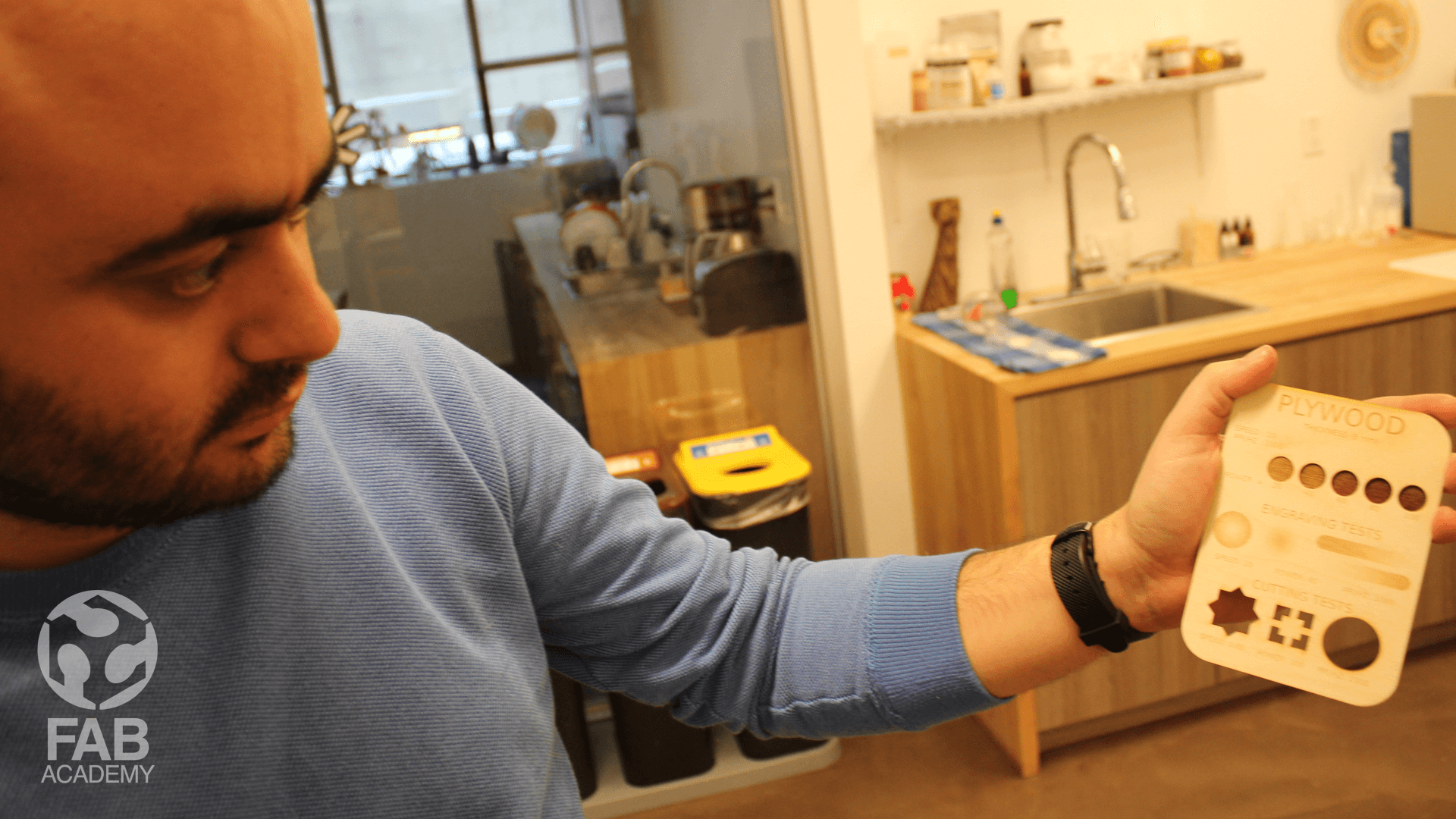
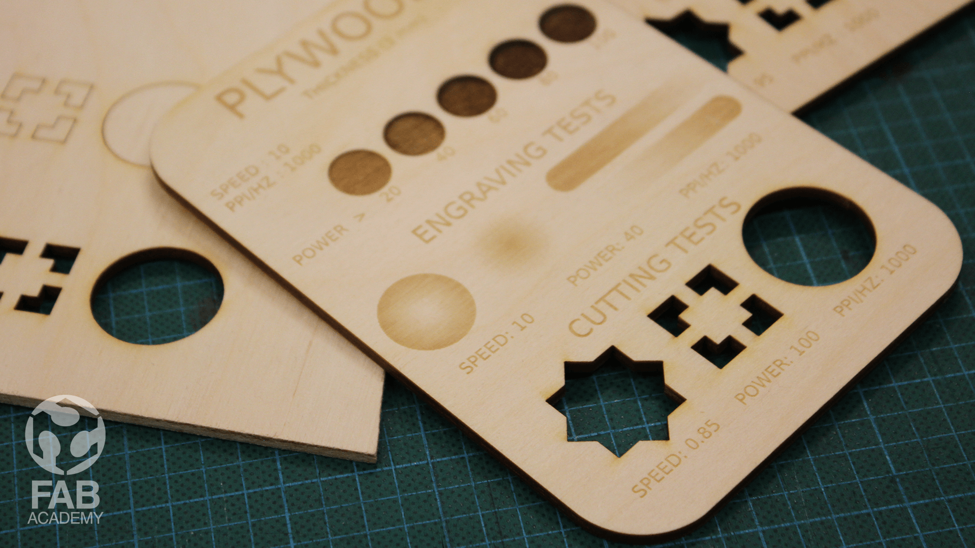
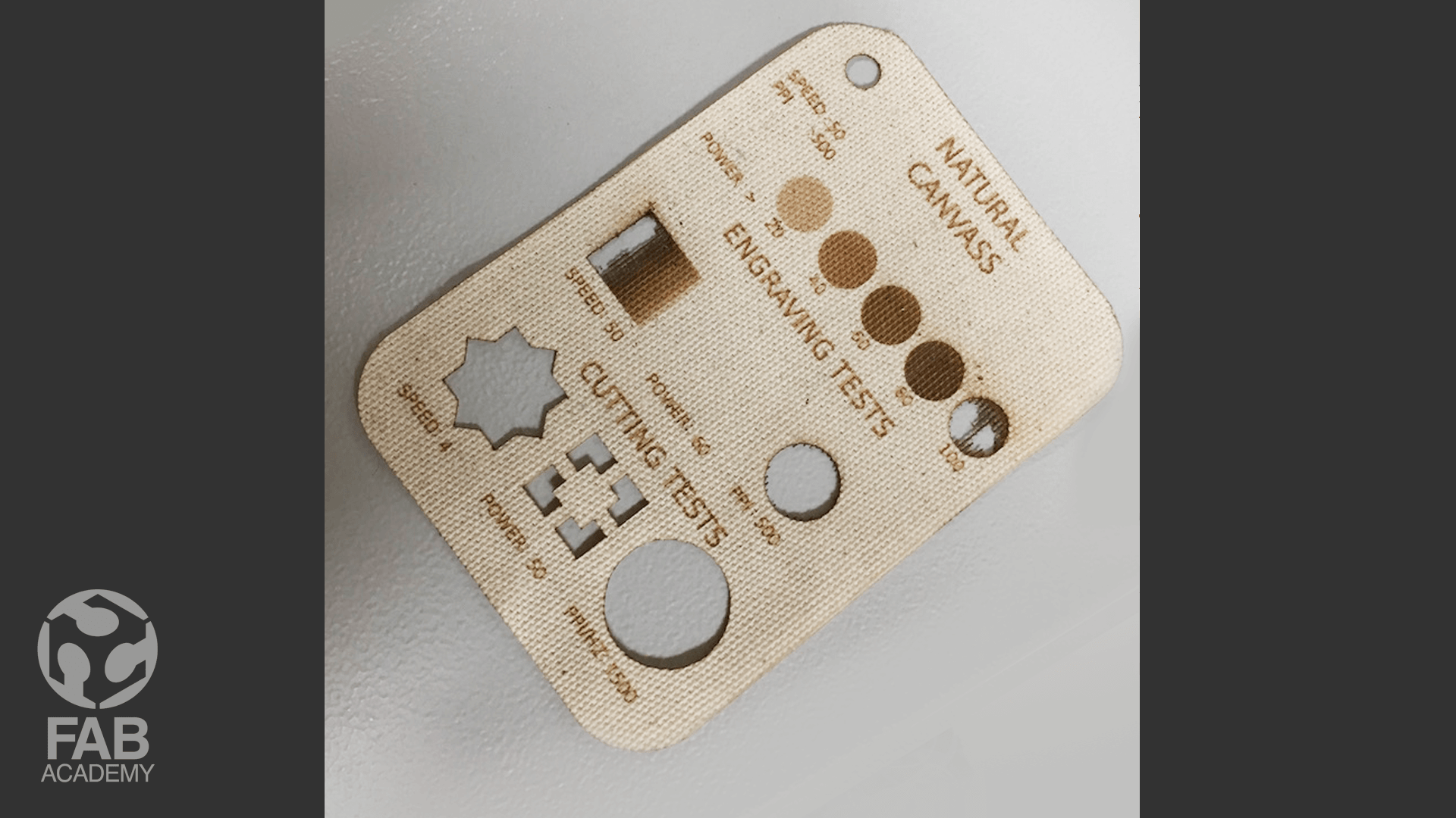
As a group we decided to run a few tests using the laser cutter on different kind of materials to better understand the process, specs and the work flow so for these reasons we prepared a test file using Adobe Illustrator. The file combined different vector shapes for engraving and cutting in different settings using different materials.
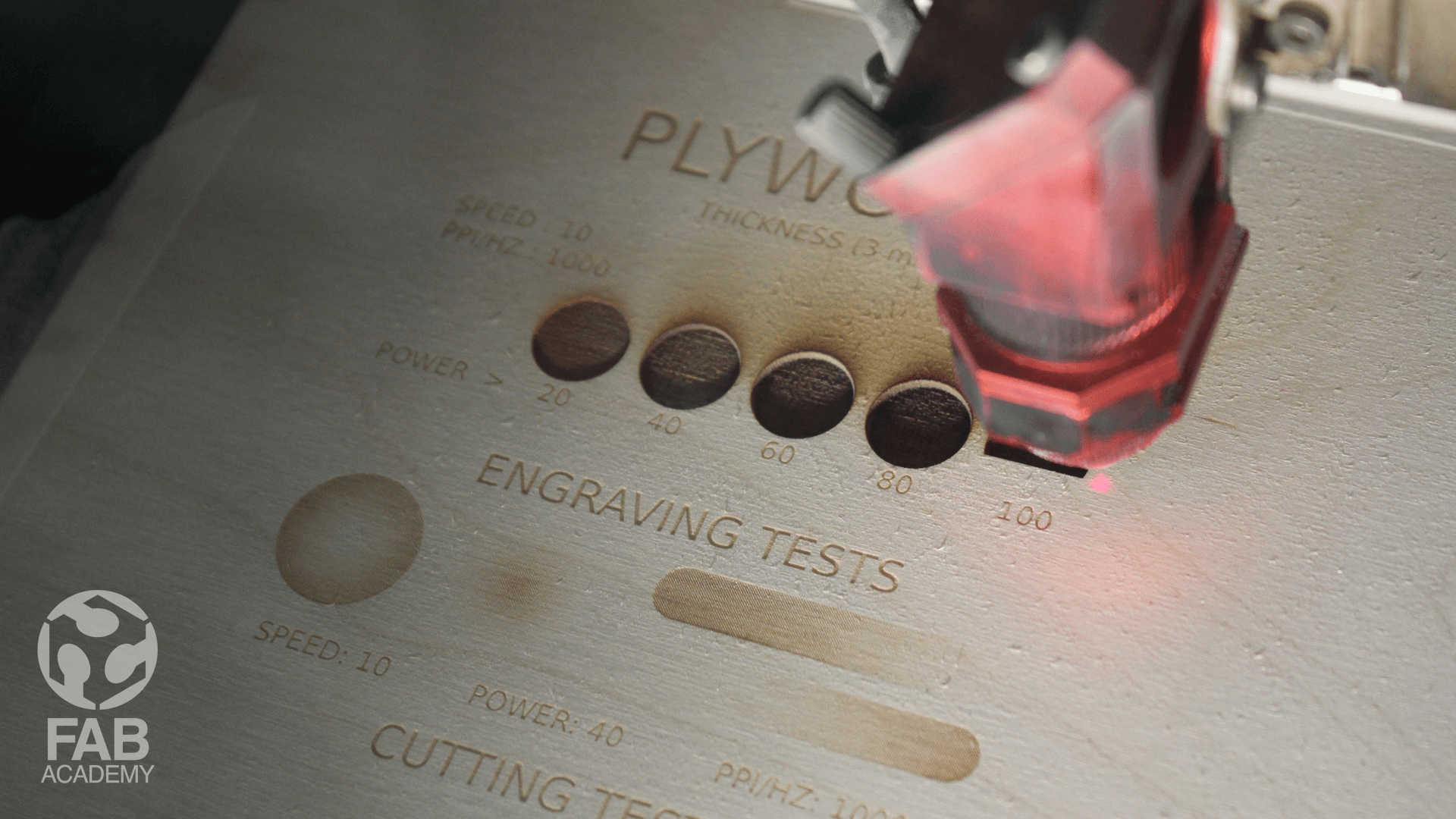
As you see in image # 07 we used color coding to tell the machine to adjust its power based on the RGB value that we specified and Image #10 shows the variety of engraving depths among the 4 circles.
USING THE VINYL CUTTER (ROLAND CAMM)
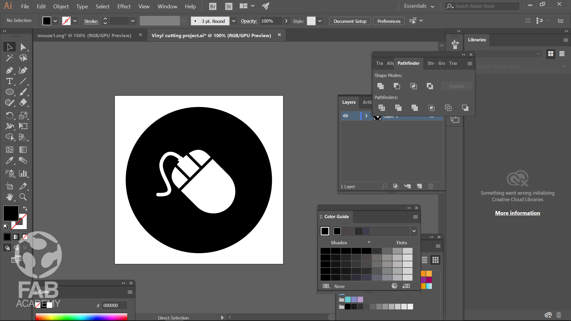
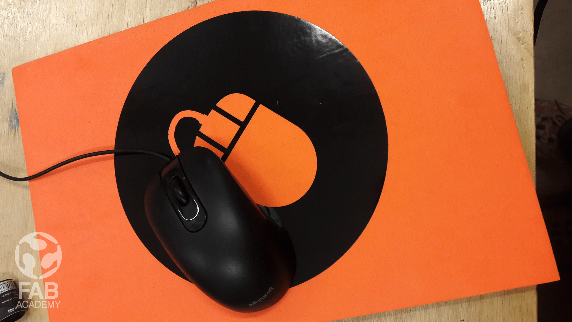
The aim of this project is to design an artwork in vector format using Adobe Illustrator or any other software and use the vinyl cutter machine for cutting the desirable design. To start with first I decided that I want to make a very simple vinyl sticker for my mouse pad so first I started with drawing the shapes in Adobe Illustrator and then I opened the file in Roland cut Studio the first trial went bad because of the wrong settings I used ( force=20 and speed= 15mm/sec ) so after re-adjusting the force to 90 and the speed to 1mm/Sec the end result was very satisfying.
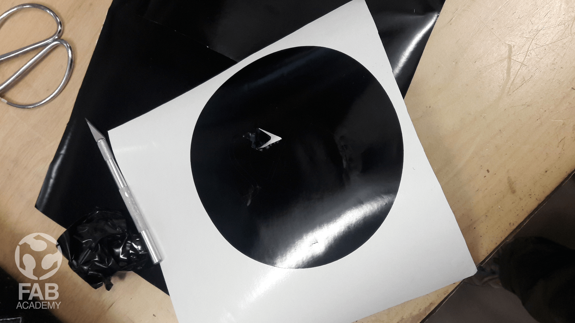
After the cutting part was done I carefully removed the excess vinyl by using a duty knife as shown in image # 19 .
USEFUL TIPS & LINKS
+ How to use JobControl X - Part 1 The Basics HERE.
+ How to use Vinyl Cutter Roland GX-24 HERE.
DOWNLOAD SECTION
+ REF_Template PLYWOOD_12_2-2018.svg DOWNLOAD .
+ W4_Pressfit construction kit v10.f3d DOWNLOAD .
+ W4_Vinyl cutting project_01.ai DOWNLOAD .
+ W4_Pressfit construction kit v10.dxf DOWNLOAD .
+ W4_Vinyl cutting project_01.eps DOWNLOAD .